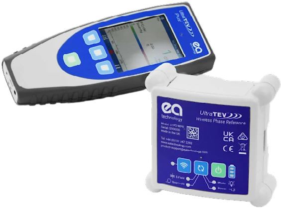
New EA Technology Wireless Phase Reference Accessory (UTP2-WPR)
In high voltage insulation systems phase plot is critical to understanding partial discharge.
What is Phase Plot?
Phase Plot is phase resolved partial discharge (PRPD) pattern; it is a visual representation of partial discharge (PD) activity relative to the 360 degrees of an AC cycle.
What Is Partial Discharge (PD) Activity?
Partial Discharge (PD) activity will be caused by some sort of defect within, or on the surface of, a high voltage (HV) insulation system.
These defects can include:
- Voids
- Gaps
- Splits
- Physical sharp points
- Imperfections etc on/within HV assets
The defect itself discharges as it is not able to insulate the voltage applied across it.
How do I interpret a PRPD pattern?
A PRPD plot shows the amplitude of each discharge event (vertical axis) plotted against their phase angle (horizontal axis).
As the primary voltage on a power system rises and falls over time, the voltage applied across each defect also rises and falls over time - causing the defect to discharge only at certain times and amplitudes. This is what creates the PRPD pattern.
Although the type of discharging defect will take on a recognisable shape, each PRPD pattern will be unique and common trends can still be seen in each defect type; PRPD patterns are the most useful tool in analysing and diagnosing PD activity within HV insulation systems.
Why Do I Need To Achieve Accurate Phase Lock?
Achieving accurate phase lock is essential because it aligns partial discharge (PD) activity with the exact point on the AC voltage cycle at which it occurs. Without that reference, PD signals can appear random, making it difficult to separate genuine insulation defects from background noise or interference. A precise phase lock ensures that each discharge is plotted consistently against the waveform, producing reliable phase-resolved partial discharge (PRPD) patterns.
With accurate phase lock you can:
- Establish a “true” phase reference that improves the clarity of diagnostic data.
- Distinguish between different types of defects, since many fault mechanisms have characteristic phase relationships.
- Compare results across multiple surveys and assets with confidence.
- Support better trending and asset management decisions by reducing ambiguity in readings.
- In short, accurate phase lock provides the foundation for trustworthy PD analysis and is critical for making informed decisions about high voltage asset condition.
- This device ensures perfect phase reference (also know as phase-lock) every time. It does this through multiple methods (mains power connection, e-field, Rogowski coil and photosensor)
- This device enables convenient wireless connection to the UltraTEV Plus2, with a range of up to 40 metres.
- This device has long battery life, up to 16 hours usage which promotes uninterrupted work-flow
"The newly launched Wireless Phase Reference Accessory (UTP2-WPR) helps engineers achieve an accurate phase lock in any environment!"
Wireless Phase Reference Means Clearer PD Insights, Faster Decisions
When screening substations, the line between noise and actionable partial discharge (PD) insight often comes down to phase locking. EA Technology Phase Reference provides a reliable, portable way to lock to mains phase so UltraTEV Plus² measurements align and stay comparable. It tightens on-site interpretation, reduces ambiguity, and accelerates decisions.
Reliable Wireless Integration
EA Technology Phase Reference integrates with UltraTEV Plus² and connects wirelessly, so the instrument can sit where readings are strongest while the sensor sits where the reference is clean. The link works to around forty metres in typical substations, keeping crews mobile while maintaining synchronisation. A long-life internal battery provides up to sixteen hours of operation, covering extended survey days without swapping gear.
Multiple Phase Lock Methods
Critically, EA Technology Phase Reference supports four ways of establishing phase lock. Clip to the mains supply; use the built-in electric field pickup; wrap a Rogowski coil around a convenient conductor; or point the front-mounted photo sensor at a fluorescent fitting where line of sight exists. That flexibility delivers a stable reference in challenging yards, indoor rooms, or mixed environments.
Cleaner Data and Trending
With a dependable reference, UltraTEV Plus² can fully exploit phase plots and waveform capture to separate genuine PD from interference. Operators gain cleaner trend data and more confidence when classifying activity and prioritising remedial work. Keeping everything phase-aligned also strengthens comparisons between assets and across repeated surveys.
Seamless Workflow Integration
EA Technology Phase Reference is practical too. The accessory is quick to deploy and aligned to typical workflows: enter asset details, capture readings, and transfer results to corporate systems via Wi-Fi, USB, or SD card for review. That continuity, from capture to analysis, helps organisations embed condition-based maintenance without adding friction.
Scaling with Condition Monitoring
As programs mature, EA Technology Phase Reference scales easily. It pairs with UHF scanning to locate internal PD sources in instrument transformers, circuit breakers, and cable sealing ends, supporting safer operations and preventing costly failures. Teams can survey whole switchyards in minutes, then return with targeted plans backed by phase-aligned evidence stakeholders can review confidently.
Hardware and Phase Reference Features:
| Hardware Features: |
|
| Size |
115 x 118 x 50mm |
| Weight |
5200g |
| Enclosure |
Injection moulded plastic case |
| Connectors |
1x GCS1 Current Sensor (for a cable of 1.5m in length)
1x Power Barrel connector |
| Mounting Mechanisms |
Magnets in feet for metallic surfaces
Velcro Strap to wrap around cables (up to 100mm diameter) |
| Indicators |
4 x LEDs to indicate current Phase Reference Source
1 x bicolour LED for Wi-Fi/WPS status
1 x LED to indicate charging status
3 x LEDs for the Battery Level |
| Controls |
3 x Push Buttons |
| Phase Reference Features: |
|
| Sources |
Mains Input Power
Lighting (Photo sensor)
Electric field (High-Z sensor)
Rogowski Coil |
| Frequency Range |
50 Hz ± 1%, 60 Hz ± 1% |
| Accuracy |
±5deg |
VIEW DATA SHEET
VIEW THE WIRELESS PHASE REFERENCE ACCESSORY
The Takeaway
Ready to raise confidence in every reading? Choose EA Technology Phase Reference to anchor PD surveys, strengthen analytics, and standardise practice across your fleet. With EA Technology Phase Reference in the kit, you elevate how your organisation discovers, interprets, and acts on PD. When the question is “is it PD or just noise?”, EA Technology Phase Reference provides the clarity you need.
Adopt EA Technology Phase Reference today to turn faster surveys into safer, smarter network decisions.