Power Factor & Other Power Quality Issues
Understanding the basic issues of Power Quality and how to address them. In this blog post we will cover the following Power Quality topics:
Power Quality: Dips and Swells
Power Quality: Electrical Interference
Power Quality: Voltage Imbalance
Power Quality: Power Factor
Power Quality: Dips and Swells
If electrical equipment is to operate correctly, it requires electrical energy to be supplied at a voltage (and frequency) that is within a specified range, and to help ensure this, European standard EN50160 "Voltage characteristics of electricity supplied by public distribution systems" was drawn up by CENELEC in November 1994. This standard lays out the main characteristics of the voltage at a customer’s supply terminals in public low-voltage and medium-voltage electricity distribution systems under normal operating conditions.
The standard prescribes the limits within which the voltage can be expected to remain but does not fully describe the typical situation in a public supply network. The limits are however quite wide (230 V ±10% for single phase supplies) and it is permissible for the voltage to drift outside the ±10% band for up to 5% of the time.
In practice, what really matters is not whether the voltage of a supply meets or does not meet the requirements of a standard, but whether it is compatible with the loads that are connected to that supply. Sometimes this is not the case, and the most common reasons are voltage dips and swells.
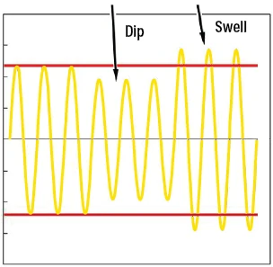
What are voltage dips and swells?
A voltage dip, which is also sometimes called a voltage sag, is a sudden reduction in the supply voltage of between 10% and 90%, which lasts for between 10 ms and 1 minute. The depth of a voltage dip is defined as the difference between the minimum RMS voltage during the dip and the declared supply voltage. Voltage changes that reduce the supply voltage by less than 10% are not considered to be dips.
Voltage dips may be caused by external factors on the supply network or internal factors within an installation. They can be single events that occur at random, or a series of events that repeat in some sort of pattern. In all instances, monitoring and recording the supply voltage over time will show exactly what is happening and help to locate the cause. External factors are more likely to produce single events and include load switching and fault clearance in the supply network. A similar effect can occur when switching between the mains supply and uninterruptible power supplies or emergency back-up generators. Common causes of voltage dips within an installation are the switching of large loads, such as motors, arc furnaces and welding equipment, and the operation of loads with fluctuating current demands. Often voltage dips produced within an installation occur at regular intervals or at particular times.
The effect that dips have on electrical equipment and building occupants varies widely and is dependent on the factors that include the nature of the event and the type of equipment connected to the supply system. In an office lit by fluorescent luminaires, which uses equipment with switch-mode power supplies and has a UPS system, it is perfectly possible that even quite severe dips will pass unnoticed. However, a similarly equipped office with a different type of lighting, older equipment with linear power supplies and no UPS, might well experience considerable disruption.
Supply voltage dips can cause particular problems, with varying degrees of severity, for AC induction motors. As the supply voltage to the motor decreases, its speed tends to decrease. Depending on the depth and the duration of the voltage dip, the motor may return to its normal speed when the supply voltage recovers. If the magnitude of the dip or its duration exceed certain limits, however, the motor may stall, or it may be disconnected from the supply by a contactor dropping out or the operation of an undervoltage trip. For motors fed from a variable speed drive, the drive may shut down to prevent potential motor damage.
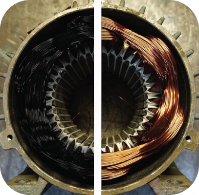
Voltage swells are the opposite of dips and are defined as a sudden increase in the supply voltage of 10% or greater for a short period, after which the voltage returns to its normal value. Once again, the time period for a swell is generally taken to be between 10 ms and 1 minute. Swells are almost always caused by a large load being switched off somewhere on the power supply network or in the local installation. Although the effects of dips may be more noticeable, voltage swells are often more destructive. Regular and sustained voltage swells can cause insulation degradation in induction motors because of the increases in current flow and heat generation, with this degradation ultimately leading to premature failure of the motor. Swells can also cause breakdown of components in power supplies due to cumulative overload effects, and damage to electronic equipment, which is often sensitive to overvoltage.
Fortunately, there are ways to mitigate the effects of dips and swells but an essential first step is always to locate the cause of the problem. This is achieved by conducting a site survey, which involves moving around the electrical installation, measuring current and voltage at various locations and using this information to identify the source of the dips and swells.
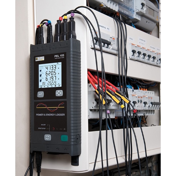
Site surveys are most easily performed with a modern power and energy logger (PEL) or power quality analyser. These instruments can be connected quickly and nonintrusively to distribution boards and other key points within the installation and left in place to gather and record information. In many cases, there is no need to even turn the power off while connecting the instrument. If monitoring shows that the problems are coming from the external supply, and voltage limits laid down for the public supply are being exceeded, then it’s time to call your electricity supplier. However, in many cases the source of the problem will be found to be within your own installation and, once you’ve identified the equipment causing the dip or swell, you can start to consider remedies.
These might, for example, include supplying the equipment in question from a dedicated circuit, installing a UPS or, in the case of motors, fitting a soft start or variable speed drive to reduce sudden changes in the current the motors draws from the supply during starting. If these remedies prove impractical or ineffective, it may again be time to call your electricity supplier to see whether a more resilient service can be provided.
Power Quality - Electrical Interference
Electrical interference is more formally known as either electromagnetic interference (EMI) or radio frequency interference (RFI). If we’re being pedantic, EMI is the more general term because, strictly speaking, RFI applies only to interference over the band of frequencies used for radio transmissions. However, for our purposes, the two terms are interchangeable and in the remainder of this section we’ll simply refer to EMI.
EMI is generally much less harmful than transients. Its effect is typically to make equipment malfunction temporarily rather than to cause permanent damage. Nevertheless, equipment malfunctions are often costly and disruptive, so EMI is not a trivial matter. EMI can come from a variety of sources including radar, TV, radio, mobile phone and microwave transmitters, and from less obvious external sources such as solar magnetic storms and radio signals produced by distant thunderstorms. External EMI can enter an electrical installation by electromagnetic induction, electrostatic coupling or conduction. EMI can also be generated by equipment within an installation, although modern appliances and equipment should be manufactured in compliance with electromagnetic compatibility (EMC) standards that minimise the risk of EMI generation.
Power and lighting equipment is unlikely to be directly affected by EMI, although electronic devices used to control this equipment may be susceptible. EMI is most often experienced as noise or hiss on audio equipment and as picture disturbances on television screens. Other common effects that are less immediately apparent include degradation of the performance of data networks and even completely stopping these networks from functioning. This can lead to increased error rates and potentially total loss of data. It’s important to note that EMI can be transmitted by crosstalk between cables that run close together. For this reason, care should always be taken to segregate power and data cables and, where appropriate, to use screened cables.
A wide variety of products are available to block EMI and prevent it from entering equipment. These include EMI suppression filters and AC line filters, as well as ferrite cores and microwave absorbers. Such devices are only effective against conducted EMI. Efficient shielding – enclosing sensitive equipment in an earthed conductive box – is the best precaution against radiated and induced EMI, so for a complete solution a combination of shielding and filtering is required.
If you suspect you’ve got problems with EMI, it’s time to get a power quality analyser and set it up to monitor the installation. EMI will be visible superimposed on the mains waveform, although it may be intermittent in nature and therefore only revealed by logging for a period of days or weeks.
Power Quality - Voltage Imbalance
Voltage imbalance is a power quality issue that often receives little or no attention. This is very unfortunate because, as we shall see, an unbalanced supply can have serious consequences. Of course, if your business only has single-phase loads, imbalance isn’t an issue for you, and you can safely skip this section. If you have any three-phase loads however, you would be well advised to read on!
In a balanced three-phase ac power system, the voltages in all three of the phases are equal in magnitude and the phases are 120 degrees apart. In an unbalanced system, the phase voltages are not equal, and/or the phases are not 120 degrees apart. Voltage imbalance is more common than a phase shift and is typically caused by big single-phase loads, such as EV charge points, induction furnaces and some traction systems.
These single-phase loads may be connected between one of the phases and the supply neutral, when they draw power from just one of the three phases, or they may be connected between two phases, when they draw power from two of the three phases.
Either way, the three phases are loaded unequally and the voltage on the phase or phases that are heavily loaded will drop. This voltage reduction will be seen as voltage imbalance by all other items of equipment that are connected to the same supply system.
Uneven distribution of even quite small single-phase loads across a three-phase system can, if there is enough of them, cause a slight voltage imbalance. This situation often develops over time when extra circuits are added to an installation that was originally balanced during its construction. Unequal degradation of power factor correction capacitors in a bank or even complete failure of one or more of the capacitors is another source of imbalance, and temporary imbalances can be produced by a fault on one of the phases either within the facility or further back up the supply network.
Having balanced phase voltages is arguably one of the most important requirements for an industrial installation, particularly if it uses three-phase motors, and crucially if they are operating at or near their full load capacity. With a fully loaded motor, unbalanced voltages at motor terminals can cause a percentage phase current imbalance up to 10 times the percentage voltage imbalance. This means that motors operating on unbalanced supplies must be significantly de-rated, even if the voltage imbalance appears to be relatively minor. Imbalance can also make it necessary to de-rate power cables because of increased I2R losses.
According to the IEC, voltage unbalance is defined as the ratio of negative sequence voltage to the positive sequence voltage. Briefly explained, the three phase voltages can be mathematically expressed as a sum of positive, negative and zero sequence components. Positive sequence voltages create a magnetic flux within the motor that rotates in the direction that the motor is intended to rotate, while negative sequence voltages create a flux that rotates in the opposite direction. Since the positive sequence voltages are always much greater than the negative sequence voltages (provided that the motor has been connected up correctly!) the direction of rotation of the motor is not affected.
The counter rotating flux caused by negative sequence voltages creates additional heating in the motor windings that may eventually lead to insulation breakdown and premature motor failure. Continuous operation at 10° C above the recommended operating temperature can reduce the life of a rotating machine by a factor of two, and reduced motor operating life is almost always disruptive and expensive.
The importance and prevalence of this problem is confirmed by the large number of businesses that develop and manufacture devices to monitor voltage imbalance as an aid to protecting motors.
As well as the motors themselves, many solid-state motor controllers and inverters include components that are sensitive to voltage imbalance. Depending on the product, some of these will protect themselves and the motor by shutting down if they detect a significant voltage imbalance but, while this safeguards the equipment, the resulting disruption can still be costly. In less sophisticated products that don’t automatically shut down, voltage imbalances are a common cause of reduced life of front-end diodes and bus capacitors.
Uninterruptible power supplies (UPSs) and inverter supplies also operate with reduced efficiency when presented with unbalanced supply voltages, often producing increased ripple on the DC output and, in many cases, increased harmonic currents in the supply system.
Since voltage imbalance can have so many harmful effects, it’s not surprising that it is covered by national and international standards. IEC 60034-1, for example, imposes a 1% negative phase sequence voltage limit on the supply feeding machines. However, EN 50160 states that imbalances of up to 3% can be expected, and indicates that an acceptable supply system standard is that "under normal operating conditions, during each period of one week, 95% of the 10-minute mean rms values of the negative phase sequence component of the supply voltage shall be within the range 0 to 2% of the positive phase sequence component".
Fortunately, the measurement of voltage and load (current) balance, and therefore the identification of imbalance, is easily achieved using a power and energy logger (PEL). With a PEL connected at the incoming supply, the loading across the phases for the whole installation can be monitored over time to see how it varies during the normal operating day or week. PELs can be quickly moved around the installation, non-intrusively connected, and used to measure individual equipment or circuit loads and voltages to achieve balance throughout the installation. They can then be reconnected to the incoming supply for ongoing monitoring not only of voltage balance but also of other important supply parameters such as harmonics and power factor.
To reduce voltage imbalances and its effects, there are two key steps. The first is to use separate circuits for large single-phase loads and connect them as close as possible to the source of the supply. This will ensure that the single-phase load does not cause a voltage drop on any wiring used by other equipment. The second step is to ensure that all single-phase loads, large and small are distributed evenly across all three phases. These two steps can save a lot of headaches and expense.
To reduce voltage imbalances and its effects, there are two key steps. The first is to use separate circuits for large single-phase loads and connect them as close as possible to the source of the supply. This will ensure that the single-phase load does not cause a voltage drop on any wiring used by other equipment. The second step is to ensure that all single-phase loads, large and small are distributed evenly across all three phases. These two steps can save a lot of headaches and expense.
Power Quality: Power Factor
Like voltage imbalance, power factor is rarely considered to be a power quality issue but it most definitely should be because poor power factor is very common, it means that businesses pay large sums of money for energy they don’t and can’t use, and it’s relatively easy and inexpensive to put right!
Poor power factor is not a new issue; for decades, experienced engineers looking after industrial and commercial installations have put measures in place to ensure that their sites had a good power factor. But today, fewer and fewer sites have such engineers to take care of them and, as a result, power factor gets forgotten and the inevitable result is needlessly inflated energy bills. But what actually is power factor, and why is it so important?
The key to the explanation is that some types of electrical equipment used in industrial and commercial applications consume a certain amount of reactive power in addition to the real (or active) power they need to do the job for which they are intended. These are often inductive devices – that is, devices that incorporate coils of wire as part of their construction. Examples are motors, induction heaters, arc welders, compressors and most types of fluorescent lighting. It’s important to understand that the reactive power doesn’t do anything useful as far as the user of the equipment is concerned.
Technically speaking, reactive power is the vector difference between the real or active power used by a device, and the total power it consumes, which is known as the apparent power. And power factor is the ratio of the real power to the apparent power. A device with a low power factor – which is more often called a poor power factor – draws more current than a device that’s doing an equal amount of useful work but has a high (or good) power factor. Higher currents increase energy losses in the electricity distribution system, so energy suppliers penalise customers that have a poor power factor by charging them more for their electricity.
Reactive power is measured in kVAr (kilovolt-amperes reactive), active or real power is measured in kW (kilowatts) and apparent power is measured in kVA (kilovolt-amperes).
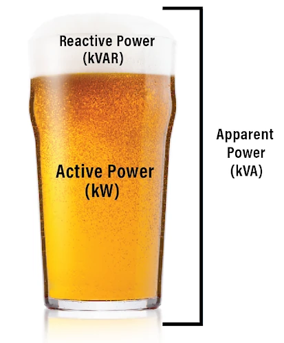
Speaking less technically, this scenario can be made easier to understand by likening it to beer! If you order a pint of draught beer, the whole glass you pay for is equivalent to the apparent power. But take a closer look – that beer has got a frothy head on it! The beer is the part you really want, and that’s equivalent to the active power, while the head, which makes no contribution to your refreshment, is equivalent to reactive power. A pint glass full of beer, with no head, would represent a power factor of 1 with no reactive power at all. In reality, that’s usually impossible to achieve and a power factor of 0.95 (corresponding to less than 5% froth!) or better is usually considered acceptable.
So far, so good, but if electrical equipment inherently consumes active power, what can be done about it? Fortunately, it is possible to correct for power factor by adding, logically enough, a power factor correction (PFC) system. This usually takes the form of capacitors connected at the main distribution board, or sometimes at other locations.
Many sites will already have some form of PFC but, as implied earlier, it is not quite a fit-and-forget solution. If more equipment is installed on a site, or the type of equipment used on the site is significantly changed, the PFC system may no longer be adequate. It’s also worth noting that capacitors used for PFC can degrade over many years of service and may eventually need to be replaced.
In fact, according to The Carbon Trust it is not uncommon for industrial installations to be operating with high levels of reactive power giving power factors of between 0.7 and 0.8. This is surprising and totally unnecessary since measuring power factor is not at all difficult. It can be readily measured using portable test instruments, or alternatively, can be permanently monitored in real-time with constantly displayed values, along with a multitude of other useful parameters including voltage, current and energy consumption.
While specification of a PFC system to reduce reactive power requires knowledge of several factors including the voltage level and typical usage of the reactive loads on-site, the usage profile across the site, and the power quality required by the on-site loads, all of these are easily measured and/or calculated. And a properly designed PFC system will be a fraction of the cost of the savings it delivers.
The simplest form of PFC involves fitting capacitors, but it is worth shopping around and taking expert advice to find a system that will accurately suit your particular requirements.
If a single machine has a poor power factor, capacitors can be connected in parallel with it, so that they compensate for the poor power factor whenever the machine is switched on.
Alternatively, if the power factor of a site is permanently poor and no single item of equipment is solely responsible, fixed PFC can be connected across the main power supply to the premises.
In more complex applications, where many machines are switched on and off at various times, the power factor may be subject to frequent change. In this case the amount of PFC needs to be controlled automatically by switching banks of capacitors into and out of circuit, as required. And in facilities with large non-linear loads, with their associated harmonic currents, it may be necessary to use a de-tuned PFC system. Numerous solutions are available on the market to provide such functionality, but expert advice should always be sought if you are in any doubt.
The Power Quality Blog Post Series by Chauvin Arnoux
In practice, almost all power quality issues can be divided into 6 main areas and our Power Quality Series ('Understanding The Basic Issues of Power Quality and How to Address Them!') covers these 6 main areas:
- Harmonics
- Dips and swells
- Transients (spikes)
- Electrical interference
- Voltage imbalance
- Poor power factor
VIEW POWER QUALITY LOGGERS