Understanding Soil Electrical Resistivity Testing
A soil electrical resistivity test determines how much the soil resists electrical current flow. It‘s essential for safe and effective grounding system design, especially for substations, renewable energy installations, and lightning protection systems.
The Megger DET4 series employs the Wenner method—the standard four-point probe technique:
ρ=2πAR
Where:
ρ = resistivity (Ω-m) A = distance between spikes (m)
R = measured resistance (Ω)
This method calculates resistivity based on current injection and voltage measurement, ensuring precise characterisation of soil conditions for engineering and safety designs.
The Megger DET4TR2 and Megger DET4TC2 models ensure precise readings by automatically checking for voltage interference and poor spike connections before every test, streamlining the entire process.
Additional Benefits Worth Highlighting
One often overlooked advantage of the Megger DET4 series is its support for field efficiency. With its backlit display and rugged build, you can keep testing even in poor lighting or harsh weather. The tester‘s automatic checks for probe resistance and environmental noise help minimise retests and false results, saving valuable time on-site.
Furthermore, Megger’s commitment to safety is clear: each tester includes automatic voltage detection and alerts, so users are never surprised by stray voltages. The selectable voltage output means agricultural users can stay compliant with regional regulations, especially where animal safety is involved. Whether you‘re working on a wind farm or a telecom substation, the Megger Earth Tester lets you test with confidence.
Real-World Use Cases and Insights
Field technicians regularly report the ease of switching between traditional fall-of-potential methods and clamp-based ART testing.
One user noted, "We no longer lose time unbolting grounding systems. The clamps save at least an hour per site!"

In another example, a university electrical lab adopted the Megger DET4TC2 as part of their curriculum. Students learned both theory and practical application, gaining hands-on experience in using a professional soil electrical resistivity tester before stepping into the workforce. These real-world testimonials reinforce the DET4’s value across all levels of experience and application.
Making the Most of Your Megger Earth Tester To keep your Megger DET4TC2 or Megger DET4TR2 operating at peak performance:
Store in its rugged carry case to protect against dust and moisture. Calibrate annually to ensure measurement accuracy. For best stakeless results, always leave at least 100mm between I and V clamps. Refer to Megger’s detailed guides for troubleshooting or advanced testing methods. Remember, proper grounding isn‘t just a technical requirement; it‘s critical for safety and compliance. The Megger Earth Tester ensures that your systems perform exactly as designed.
Conclusion:
The Ultimate Soil Electrical Resistivity Tester The Megger Earth Tester DET4 series offers unmatched performance and flexibility for all forms of soil electrical resistivity testing. With the Megger DET4TC2 and Megger DET4TR2, users gain access to premium features, including selectable voltage output, automatic spike checks, and compatibility with advanced clamp accessories.
Whether you need a dependable soil electrical resistivity tester for academic use, civil engineering projects, or routine maintenance, the Megger Earth Tester, particularly the Megger DET4, is your go-to solution. Experience accuracy, durability, and user-friendly design—all in one instrument. For consistent and trustworthy soil electrical resistivity test results, choose the Megger DET4 series and elevate your testing capabilities today.
The Clamps: Further Reading:

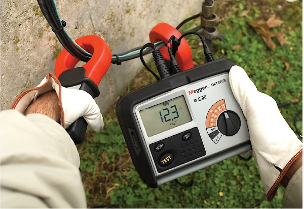
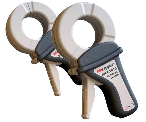
The Megger DET4TC and DET4TCR earth testers introduce advanced and efficient methods for testing earth resistance, specifically the Attached Rod Technique (ART) and “Stakeless” testing. Traditionally, measuring earth resistance required disconnection of electrodes, which could lead to downtime and safety concerns. ART eliminates this by allowing testing without disconnection, using the MCC1010 to isolate and measure current specifically through the electrode under test.
In ART mode, the instrument injects a 128 Hz test current and measures the voltage and current at the same frequency, filtering out interference from other sources. If the resistance of the electrode is up to 20 times higher than the rest of the system, ART can still provide accurate readings. When this threshold is exceeded, the device displays a “clamp low” warning, indicating the need for a traditional 3-pole test.
To improve flexibility, the tester includes a 4-pole plus clamp mode, which avoids lead resistance by measuring directly at the electrode. ART is highly effective for testing domestic TT systems, lightning protection electrodes, and pole-mounted transformers.
“Stakeless” testing, enabled by using both the MCC1010 and an additional MVC1010, allows users to measure electrode resistance in environments where driving test stakes is impractical. The MCC1010 induces current while the MVC1010 measures voltage, determining loop resistance. This method accounts for all connections in the loop, highlighting poor contacts and enabling long-term condition monitoring.
However, proper application is crucial. Misuse—such as forming loops that bypass the earth—leads to inaccurate or meaningless results. The document emphasizes understanding current paths for reliable measurements.
Together, ART and Stakeless methods significantly enhance safety, efficiency, and convenience in field testing, particularly for complex or restricted installations such as substations and lightning protection systems.